Advanced Garage Door Opener Diagnostics Guide


Published: Aug 27, 2026

When an overhead door system malfunctions, most standard advice covers the absolute basics—like wiping dirt off a photo-eye lens. But when you face a system that hums but won’t move, reverses intermittently, or remains completely unresponsive, you need a systematic approach to isolate the failure.

About 45% of reverse-closing errors are resolved via basic garage door safety sensor troubleshooting. However, data shows that in 20% of cases, installing brand-new sensors fails to solve the issue. This diagnostic dead-end points directly to internal electronic faults: a cracked solder joint, a blown terminal resistor, or a failing logic board microprocessor.

This guide provides the diagnostic frameworks and physical testing procedures needed to pinpoint the root cause of complex malfunctions before committing to an expensive replacement.
The Terminal Isolation Protocol


To diagnose a malfunctioning system, you must first isolate the control accessories from the primary logic board. A wall console button with internal shorts or damaged low-voltage wiring can easily mimic a dead logic board.

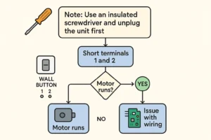
By using the Terminal Isolation Protocol, you can safely bypass all external accessories to verify whether the central receiver or processor is functional.

Terminal Isolation Protocol Flowchart

Performing the Screwdriver Test

  1. Disconnect power to the unit to ensure safety.
  2. Access the low-voltage terminal strip on the back or side of your motor head.
  3. Locate the terminals connected to your wall button (Terminals 1 and 2 on standard Chamberlain, LiftMaster, and Craftsman systems).
  4. Remove the accessory wires from these terminals.
  5. Reconnect the power.
  6. Take an insulated flathead screwdriver and briefly bridge the metal contacts of Terminal 1 and Terminal 2.

If the motor clicks, engages, and runs when you bridge these terminals, your logic board is healthy. The failure lies in a shorted wall console or damaged low-voltage wiring running along your garage walls.


Advanced Multimeter Diagnostics: Testing Low-Voltage Terminal Strips


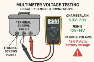
When executing electric garage door openers troubleshooting, testing terminal output voltages with a digital multimeter is the most reliable way to confirm component-level health. Set your digital multimeter to the DC Voltage setting (20V range) to measure the following brand-specific output terminals:

Multimeter Testing Sensor Terminals

Low-Voltage Target Values

  • Chamberlain, LiftMaster, and Craftsman: Test the voltage across Terminals 2 (white wire input) and 3 (grey wire input). The multimeter should register a pulsed signal measuring 6.0V to 7.0V DC. If it reads 0V, the logic board’s internal low-voltage regulator is blown.
  • Genie and Overhead Door: Test the safety sensor terminals. These loops run at a higher voltage, requiring a steady output between 12V and 14V DC.
  • Patriot & Polaris Swing Gate Systems: These operate on battery-backed low-voltage DC loops. Test the battery terminals directly. A healthy battery must read 12.6V DC static. If the reading drops below 12.2V DC under motor load, the control board will fail to cycle, often misdiagnosed as a dead motor.

Brand-Specific Diagnostic Profiler


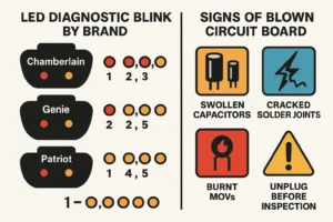
Overhead openers are vulnerable to environmental stress. Lightning strikes and utility power grid fluctuations are the primary causes of garage door opener surge damage. Unfiltered electrical spikes blow out the protective metal-oxide varistors (MOVs) or rectifiers on the primary power input stages of the circuit board.

To identify these failures on your specific system, cross-reference your unit’s symptoms with the Diagnostic Profiler below:

Opener LED Blink Codes and Physical Board Failure

Physical and Electronic Diagnostic Indicators

  • Chamberlain / LiftMaster (Security+ 2.0): Look for the yellow learn button. If the diagnostic LED flashes 1-up/1-down or 5-down/1-up, this indicates a logic board failure. For professional repairs, consult specialized liftmaster garage door repair services to ensure rolling-code receiver calibration matches factory standards.
  • Genie / Overhead Door Systems: Check physical limit switch loops. If the door refuses to stop at correct intervals, use your multimeter’s continuity mode to verify if the garage door limit switch is physically opening and closing the contact loop.
  • Patriot & Polaris Gate Openers: Inspect the solar-charging circuit board. Check the fast-acting 15A/30A ATC fuses on the main panel. If the fuses are intact but the battery fails to charge under solar input, test the charge controller output.
  • Legacy & Superjack Openers: These older units rely on heavy mechanical relay-driven boards. If you hear a click but experience zero motor rotation, inspect the board for cold solder joints around the relay pins and power transformer.

Financial Evaluation Matrix: Repair vs. Replace


When faced with component failure, deciding whether to swap individual parts or invest in a new opener comes down to unit age, safety features, and cost efficiency.

If your opener is approaching a decade of service, component replacement often acts as a temporary fix. In these cases, opting for a comprehensive garage door opener replacement yields better long-term reliability and gives you access to modern smart home integrations and battery backup systems.


Navigate Your Repairs with Confidence


Performing component-level diagnostics requires precision and the right tools. If your troubleshooting points to a complex logic board replacement, high-voltage wiring failure, or mechanical motor defect, professional intervention ensures your system remains safe and reliable.

Our experienced technicians specialize in advanced electrical diagnostics, logic board replacement, and full system upgrades. Contact us today to schedule a comprehensive diagnostic evaluation and restore your garage door system’s performance.

Advanced Troubleshooting FAQs


Can a power surge damage a logic board without showing burn marks?

Yes. Solid-state microprocessors can suffer electrostatic or over-voltage damage internally without leaving visible carbon scoring or blistered capacitors. If voltage input to the board is correct but terminal output to accessory loops is 0V, the microprocessor is likely fried.

How do I verify if my motor capacitor is dead or if the board is failing?

If the opener hums but the drive shaft doesn’t turn, the start capacitor may be blown. Visually inspect the capacitor for oil leaks or a bulged top cover. You can also test its capacitance with a multimeter set to microfarads (µF); if the reading is significantly below the rating printed on the canister, replace the capacitor.

My opener runs, but stops and reverses immediately. How do I test the limits?

This is often a limit or travel module issue. You will need to perform a manual garage door opener adjustment to recalibrate the force settings. If the opener ignores these travel limit inputs entirely, the optical travel sensor (RPM sensor) on the motor shaft is likely damaged.

How many amps should my opener pull during a normal lift cycle?

You should understand how many amps does a garage door opener use under standard load. A residential 1/2 HP AC opener typically pulls 4.5 to 5.0 Amps. If your multimeter inline amp test shows the motor drawing over 7 Amps, it indicates a binding garage door or internal mechanical motor failure.


Contact / Request a Call