When an industrial overhead door fails to move, operational delay costs rapidly mount between $1,000 and $10,000 per hour in lost logistics throughput and compromised building environmental envelopes. Isolating whether an unresponsive commercial door operator (CDO) stems from a blown control relay, a tripped limit switch, or a safety lockout requires systematically separating high-voltage motor circuits from low-voltage logic controls.
Commercial Door Operator Not Responding: Control and Limit Diagnosis
Published: Nov 9, 2026
Commercial Safety & UL 325 Lockout Protocols
Before attaching test leads, technicians must recognize the dual-voltage architecture inherent to commercial units. Industrial operators run high-voltage line power (115V, 208V, 230V, or 460V in single- or three-phase configurations) to power the motor, alongside a step-down transformer providing 24VAC and 5VDC logic bus power for control stations, limits, and safety circuits.
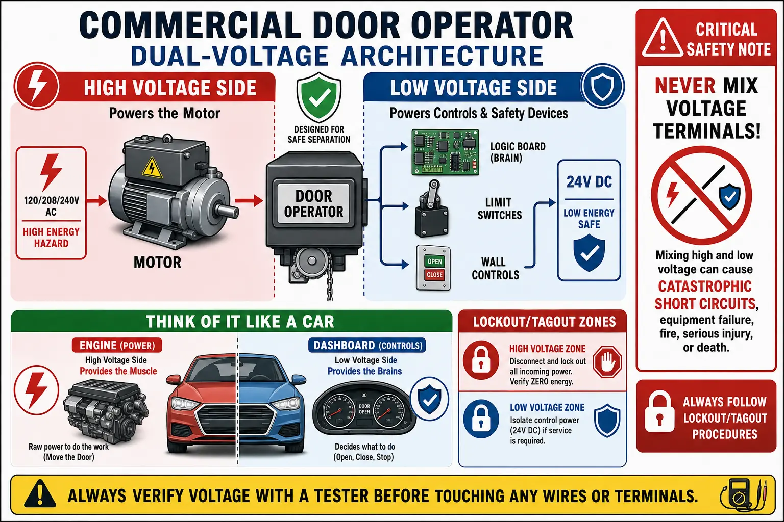
Always perform Lockout/Tagout (LOTO) procedures when servicing internal mechanical gears or high-voltage lines. Reviewing a verified commercial garage door opener wiring diagram helps verify low-voltage test points without exposing personnel to electrical hazards.
Still stuck? Get it fixed today.
24/7 emergency service from licensed local technicians.
Fast-Track Visual & Audible Fault Isolation
Field analysis reveals distinct pattern distributions across commercial operator service calls:
- 38% UL 325 Entrapment Faults: Misaligned photo eyes or blocked sensing edges forcing constant-pressure (C2) mode lockouts.
- 29% Limit Switch Misalignment: Mechanical trip cams over-traveling microswitches or faulty digital encoders losing position.
- 21% Control Wiring & Wall Station Loops: Open circuits in the 3-button station (specifically broken STOP circuits).
- 12% Control Board Failure: Burned 24VAC transformers, microcontrollers, or welded direction relays.
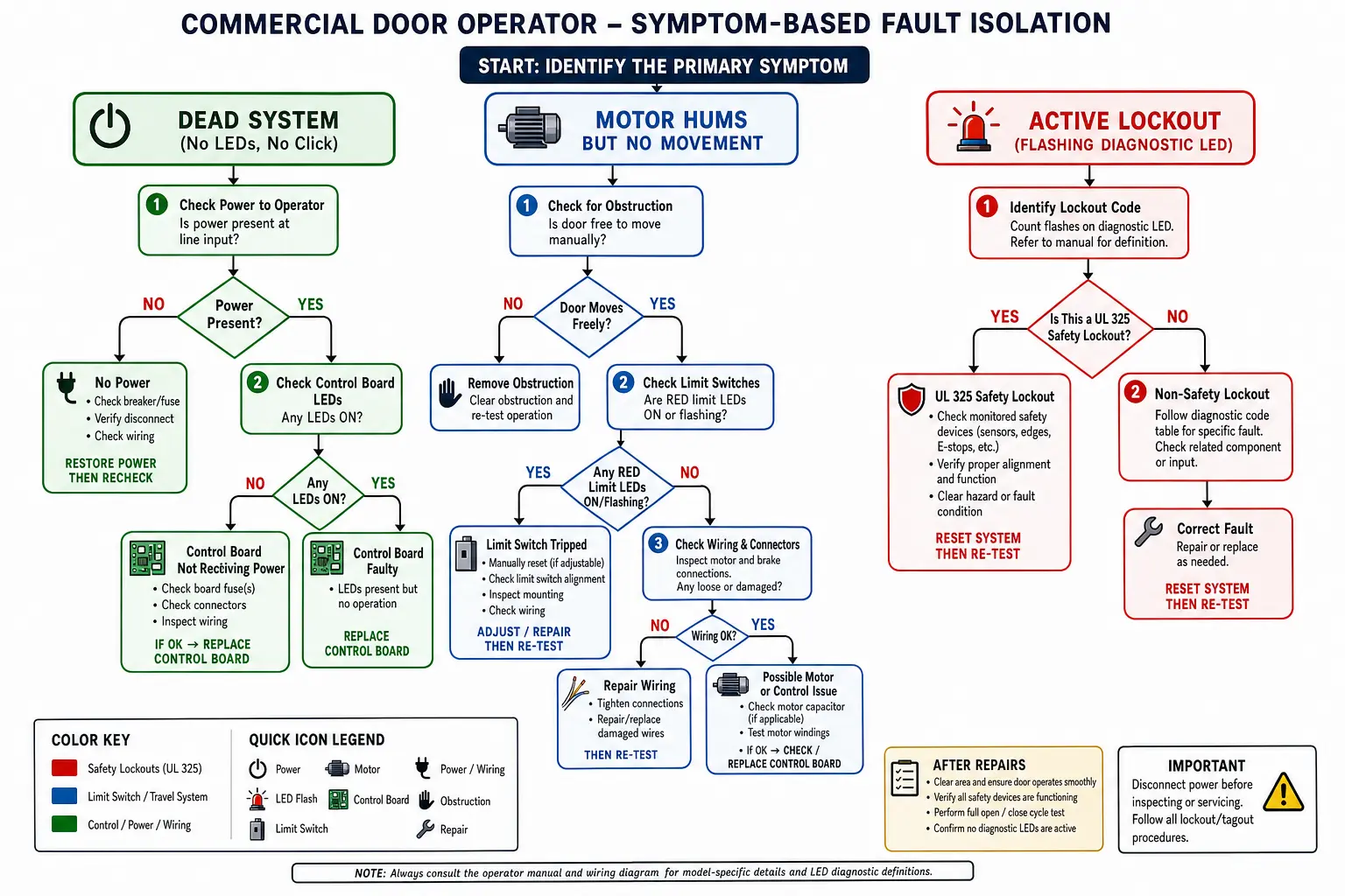
By observing board LEDs and relay clicks, you can narrow down the root cause in under two minutes:
- Dead System (No LEDs, No Relays): Check main line voltage, thermal overload cutouts, and 24VAC transformer secondary output terminals.
- Active Diagnostic LED / Flash Sequences: Refer to OEM diagnostic codes (e.g., LiftMaster MAS LED 5 flashes indicates RPM sensor/encoder errors; 7 flashes points to safety edge shorts).
- Relay Clicks, Motor Silent: Inspect direction contactors, starting capacitors, or high-voltage thermal overloads.
Step-by-Step Control Circuit and Logic Diagnostics
The single most common oversight during commercial operator diagnostics involves wall station wiring. Standard industrial 3-button stations operate on a Normally Closed (NC) STOP circuit loop. If wire integrity drops on Terminal 1 or 2, the board interprets it as an active STOP command, blocking all movement.
To test, place a temporary jumper wire across the STOP circuit terminals (Terminals 1 and 2 on standard Logic boards). If the door responds instantly to an OPEN command, replace the physical station button or multiconductor control wire.
When dealing with ongoing electrical anomalies, engaging standard commercial garage door maintenance protocols prevents premature board replacements caused by loose wiring terminals.
Limit Assembly & Encoder Verification
If control circuits test normal, focus shifts to travel limit assemblies:
- Mechanical Limit Cams: Inspect microswitch continuity using a multimeter set to Ohms. If over-travel forces trip cams past microswitch levers, manual recalibration is required.
- Digital Absolute Encoders (RPM Sensors): Modern units utilize optoelectronic encoders. Dust build-up or harness corrosion can interrupt pulses, forcing the operator to halt. Clean sensor lenses with clean air before reprogramming limits.
Ensuring smooth mechanical performance across your heavy-duty commercial garage door tracks protects both electronic limits and drive gears from binding stress.
Decision Matrix: Repair, Recalibrate, or Replace
Evaluating whether to replace individual components or order a full system overhaul depends on component costs, downtime impact, and system age.
| Diagnostic Outcome | Typical Component Cost | Labor / Downtime Impact | Recommended Action |
|---|---|---|---|
| Limit Switch Recalibration | $0 | 0.5 – 1 Hour | Recalibrate mechanical cams / reprogram encoder. |
| Limit Assembly Replacement | $45 – $110 | 1 – 2 Hours | Replace worn microswitches or cracked drive gears. |
| Logic Board Replacement | $220 – $450 | 1 Hour | Swap board (e.g., LiftMaster Logic 5) when 24VAC transformer fails. |
| Full Operator System | $1,200 – $3,500 | 3 – 6 Hours | Upgrade legacy operators exceeding 10–12 years. |
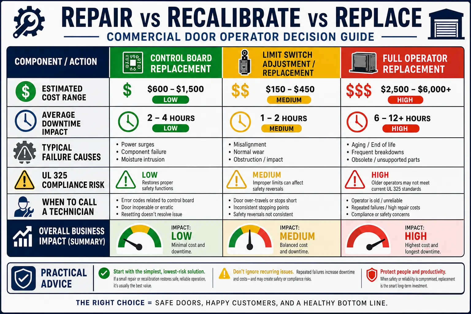
When internal components show thermal charring or persistent microcontroller locks, dispatching certified 24 hour garage door repair experts ensures safety compliance and rapid operational recovery.
Frequently Asked Questions
Why does the commercial door operator close only when constant pressure is held on the button?
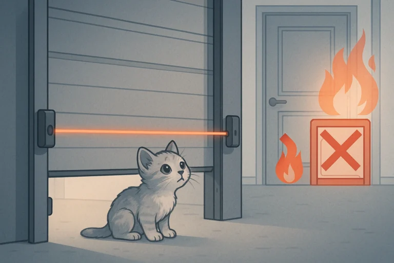
This behavior indicates a UL 325 safety lockout. When photo eyes are misaligned, dirty, or damaged, the operator defaults to C2 manual constant-pressure operation for safety compliance, blocking automatic B2 momentum close modes.
How do I distinguish between a bad logic board and a bad wall control station?
Disconnect wall station wiring from the terminal strip and place a jumper wire across Terminals 1 and 2 (NC Stop loop). Momentarily short Terminals 2 and 3 (Open command). If the operator runs, the logic board is intact and the fault lies in the wall station or wiring.
What causes a commercial door operator motor to hum without opening the door?
A humming motor typically points to a blown motor start capacitor, a tripped thermal overload, a locked mechanical brake, or a missing voltage phase on 3-phase power supply lines.